What are Valves?
Valves are mechanical devices that controls the flow and pressure within a system or process. They are essential components of a piping system that conveys liquids, gases, vapors, slurries etc..
Different types of valves are available: gate, globe, plug, ball, butterfly, check, diaphragm, pinch, pressure relief, control valves etc. Each of these types has a number of models, each with different features and functional capabilities. Some valves are self-operated while others manually or with an actuator or pneumatic or hydraulic is operated.
There are many valve designs, types and models, with a wide range of industrial applications. All satisfy one or more of the functions identified above. Valves are expensive items, and it is important that a correct valve is specified for the function, and must be constructed of the correct material for the process liquid.
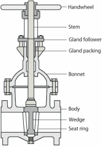
Regardless of type, all valves have the following basic parts: the body, bonnet, trim (internal elements), actuator, and packing.
Different types of valves are available: gate, globe, plug, ball, butterfly, check, diaphragm, pinch, pressure relief, control valves etc. Each of these types has a number of models, each with different features and functional capabilities. Some valves are self-operated while others manually or with an actuator or pneumatic or hydraulic is operated.
There are many valve designs, types and models, with a wide range of industrial applications. All satisfy one or more of the functions identified above. Valves are expensive items, and it is important that a correct valve is specified for the function, and must be constructed of the correct material for the process liquid.
Regardless of type, all valves have the following basic parts: the body, bonnet, trim (internal elements), actuator, and packing.
Functions of Valves
|
|
Classification of Valves
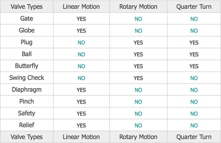
The following are some of the commonly used valve classifications, based on mechanical motion:
- Linear Motion Valves. The valves in which the closure member, as in gate, globe, diaphragm, pinch, and lift Check Valves, moves in a straight line to allow, stop, or throttle the flow.
- Rotary Motion Valves. When the valve-closure member travels along an angular or circular path, as in butterfly, ball, plug, eccentric- and Swing Check Valves, the valves are called rotary motion valves.
- Quarter Turn Valves. Some rotary motion valves require approximately a quarter turn, 0 through 90°, motion of the stem to go to fully open from a fully closed position or vice versa.
Types of Valves
Gate Valves
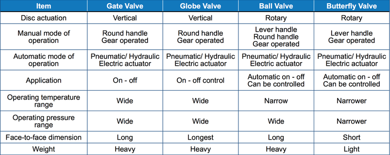
Gate Valves are designed to operate fully open or fully closed. Because they operate slowly they prevent fluid hammer, which is detrimental to piping systems. There is very little pressure loss through a gate valve. In the fully closed position, gate valves provide a positive seal under pressure. However, under very low pressure, i.e. 5 psi, light seepage would not be considered abnormal with this kind of valve.
Ball Valves
Ball Valves are also designed to be operated fully open or fully closed with any liquid containing particles that could scratch the ball. Many people use them successfully for throttling clear water. Ball valves have low pressure drops, open and close quickly, are simple, and are trouble free. With the development of Teflon seals, ball valves have grown in popularity. Opening or closing a ball valve too quickly can cause fluid hammer.
Butterfly Valves
Butterfly valves, like ball valves, operarte with a 1/4 turn. They are generally used for handling large flows of gases or liquids, including slurries, but should not be used for throttling for extended periods of time. They are also very compact relative to flanged gate and ball valves.
Globe Valves
Globe valves, as is the case with all valve designs, have both advantagesand disadvantages. Like a gate, they close slowly to prevent fluid hammer. You can throttle the flow and they will not leak under low pressure when they are shut off. Flow and pressure control valves as well as hose bibs generally use the globe pattern. The disadvantage of this design is that the "Z" pattern restricts flow more than the gate, ball, or butterfly valves.
All psi ratings apply to water, oil, or gas. Steam is usually derated by one half. (250 psi water or 125 psi steam).
Plug Valves
Like the gate valve, a plug valve has an unobstructed flow, yet requires only a 90 degree turn to open it. It also requires very little headroom. Stem corrosion is minimal because there are no screw threads. Almost all plug valves now are furnished with an elastomer-coated plug and will seal off driptight. However, plug valves are available in much larger sizes than ball valves and are highly suitable for use in wastewater plants.
Characteristics of Valves by Type:
Class Ratings
Pressure-temperature ratings of valves are designated by class numbers. Flanged, Threaded, and Welding End is one of the most widely used valve standards. It defines three types of classes: standard, special, and limited. It covers Class 150, 300, 400, 600, 900, 1500, 2500, and 4500 valves.
Valve Terminology
Solenoid Valve Terminology
Now is a good time to explain some of the terminology used in order to help you with your selection.
Ball Valve Terminology
Now is a good time to explain some of the terminology used in order to help you with your selection.
Components
2 Way Valves
2 Way / 2 position
Actuators
Pneumatic
Pressure/ Vacuum Switches
Now is a good time to explain some of the terminology used with Pressure Switches in order to help you with your selection.
Single Pole Double Throw (SPDT)
With this type of switch the electrical circuit can be "made" when the switch is activated (common to N.O.) or "broken" when the switch is activated (common to N.C.).
Single Pole Single Throw (SPST) Normally Closed
With this type of switch the electrical circuit will be "broken" when the switch is activated.
Single Pole Single Throw (SPST) Normally Open
With this type of switch the electrical circuit will be "made" when the switch is activated.
Deadband/Hysterisis/Differential are all terms used to describe the difference between when a switch activates and when it resets. Because of the mechanics of the micro-switch this is seldom at the same setting. Some of our switches have fixed deadbands (Series PMM, VCM) and others have limited adjustable deadbands (Series PSM, PSP, VSM, adjustable up to 30% of full scale).
Set Point is the setting at which the switch will activate.
Measures of Flow
Cv Imperial measure flow of vale US gallons per minute of water at 60° fahrenheit with pressure drop of 1 psi across the valve
Kv Metric measure flow of valve m³ per hour of water at temperature between 5°C & 40°C with rpessure drop of 1 Bar across valve
Qn Pneumatic flow of valve litres of air per minute at 20°C input pressure 6 Bar pressure drop of 1 Bar
Flow through a valve is calculated by the following formula;
1. Fluid
Q = 14.28cv √?P/r
where
Q = Flow (L/min)
?P = Pressure Drop
r = Density of Fluid (kg/dm^3) (water = 1kg/dm^3)
cv = Flow rating of valve
2. Gases
Q = 400cv √(P2 + 1.013) x ?P x √273/273+t
where
P2 = Outlet Pressure
t = Gases Temperature
Working out Amps/Volts or Watts
Amps = Watts/Volts
Volts = Amps x Ohms
Duty Cycle - compliance to IEC standard
Duty cylce means the starting frequency. The formula for calculating it is as follows;
Running Time / (Running Time + Rest Time) x 100% = Duty Cycle
Rest Time = Runnng Time x (1 - Duty Cycle) / Duty Cycle
For exampel the running time for 0M-2 is 15 seconds.
1. 30% duty cycle 15 x (1 - 30%) / 30% = 35 seconds rest time
2. 75% duty cycle 15 x (1 - 75%) / 75% = 5 seconds rest time.
The higher the duty cycle, the shorter the rest time.
Now is a good time to explain some of the terminology used in order to help you with your selection.
- 2 way is a two port valve that turns the flow on or off
- 3 way is a three port valve that allows flow through the valve into a chamber, and then out through the valve exhaust. The universal function can also be used as a diverter valve.
- 5/2 way is a five port, two position valve that will put a fluid or air into one end of a double acting device as well as allowing the other end vent to exhaust.
- Zero Differential are solenoid valves that can operate under zero head pressure (do not need a differential pressure drop across the valve to work). This is made up of two categories, direct acting and coupled diaphragm.
- Direct acting are solenoid valves that are activated purely by the electromagnetic forces in the valve and do not rely on the fluid pressure to assist. Hence they are used where little or no fluid pressure is available such as vacuum service or low pressure applications.
- Differential operated are solenoid valves that do rely on the fluid pressure to assist in activating the valve. This helps in developing valves with larger orifices, higher pressures and smaller coils.
- Normally closed (N.C.) means that when the solenoid valve is not energised the supply pressure port is closed off. In the case of 3 way valves the downstream port is open to the exhaust port.
- Normally open (N.O.) means that when the solenoid valve is not energised the supply pressure port is open to the downstream port. In the case of 3 way valves the downstream port is closed to the exhaust port.
- IP rating is an international standard to denote the degree of protection against water and solid objects. All of our electrical coils with DIN plugs have an IP65 rating. The '6' denotes a complete protection against items as small as dust and '5' is protection against low pressure jets of water from all directions.
- Flame proof relates to the electrical part of a solenoid valve only (usually the coil and operator assembly) and is a way of making the valve safe to use in an explosive atmosphere. These valves must be installed in compliance to the wiring standards for this type of approval and in a zone compatible to the approved code and temperature rating.
- D.I.P rating relates to Dust and Ignition Proof.
- N.B. Bar relates to pressure: 1 Bar = 14.7psi = 100KPA = 1 atmosphere.
Ball Valve Terminology
Now is a good time to explain some of the terminology used in order to help you with your selection.
Components
2 Way Valves
- 2 piece - Body manufactured from two castings and threaded together.
Advantage: Lower cost
Disadvantage: Difficult to remove from the pipe work, usually non-replaceable - 3 piece - Body manufactured from three castings and clamped with tie rods.
Advantage: Able to be removed from the pipework without disruption, repairable, usually a higher spec valve
Disadvantage: Usually more expensive
- 4 piece - Body manufactured from four castings and threaded together.
2 Way / 2 position
- Two port valve that turns the flow ON or OFF
- Three port valve that is available in two configurations
- L-port - commonly used as a flow diverter. In one position port C is connected to port A, in the second position port C is connected to port B.
- T-port - commonly used as a valve for draining or relieving the downstream pressure. In one position port C is connected to port A, in the second position port A is connected to port B.
Actuators
Pneumatic
- Double Acting (DA) - pneumatic actuator that requires an air signal to turn it ON and a second signal to turn it OFF
Advantage: Quick operation and lower cost - Spring Return (SR) - pneumatic actuator with spring return that requires an air signal to actuate - spring to close (also known as single acting). Advantage: Only a single signal required to operate - fail safe in the event of a power or air supply failure
- A motorised gearbox drives the valve. Commonly used where compressed air is not available. Slower operation - usually 12 to 15 seconds. They are available in Spring Return as well.
Pressure/ Vacuum Switches
Now is a good time to explain some of the terminology used with Pressure Switches in order to help you with your selection.
Single Pole Double Throw (SPDT)
With this type of switch the electrical circuit can be "made" when the switch is activated (common to N.O.) or "broken" when the switch is activated (common to N.C.).
Single Pole Single Throw (SPST) Normally Closed
With this type of switch the electrical circuit will be "broken" when the switch is activated.
Single Pole Single Throw (SPST) Normally Open
With this type of switch the electrical circuit will be "made" when the switch is activated.
Deadband/Hysterisis/Differential are all terms used to describe the difference between when a switch activates and when it resets. Because of the mechanics of the micro-switch this is seldom at the same setting. Some of our switches have fixed deadbands (Series PMM, VCM) and others have limited adjustable deadbands (Series PSM, PSP, VSM, adjustable up to 30% of full scale).
Set Point is the setting at which the switch will activate.
Measures of Flow
Cv Imperial measure flow of vale US gallons per minute of water at 60° fahrenheit with pressure drop of 1 psi across the valve
Kv Metric measure flow of valve m³ per hour of water at temperature between 5°C & 40°C with rpessure drop of 1 Bar across valve
Qn Pneumatic flow of valve litres of air per minute at 20°C input pressure 6 Bar pressure drop of 1 Bar
Flow through a valve is calculated by the following formula;
1. Fluid
Q = 14.28cv √?P/r
where
Q = Flow (L/min)
?P = Pressure Drop
r = Density of Fluid (kg/dm^3) (water = 1kg/dm^3)
cv = Flow rating of valve
2. Gases
Q = 400cv √(P2 + 1.013) x ?P x √273/273+t
where
P2 = Outlet Pressure
t = Gases Temperature
Working out Amps/Volts or Watts
Amps = Watts/Volts
Volts = Amps x Ohms
Duty Cycle - compliance to IEC standard
Duty cylce means the starting frequency. The formula for calculating it is as follows;
Running Time / (Running Time + Rest Time) x 100% = Duty Cycle
Rest Time = Runnng Time x (1 - Duty Cycle) / Duty Cycle
For exampel the running time for 0M-2 is 15 seconds.
1. 30% duty cycle 15 x (1 - 30%) / 30% = 35 seconds rest time
2. 75% duty cycle 15 x (1 - 75%) / 75% = 5 seconds rest time.
The higher the duty cycle, the shorter the rest time.