With so many different types of valves on the market today, it can be difficult to decide which valve is most suitable for your application. In this article, we explore the merits of ball valves versus gate valves.
Selecting the best valve can make or break your system. Ball valves and gate valves are both designed to restrict and control flow. Which gives better longevity and leak prevention though? Read on to find out.
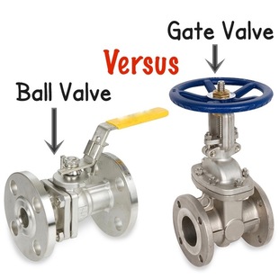
What is the main difference between ball and gate valves?
Ball and gate valves essentially perform the same function. However, their structural qualities are markedly different. Ball valves have a stem and ball, which turns horizontally, and are commonly referred to as “rotational” valves. They are best suited to applications requiring on/off control without pressure drop.
Gate valves open by lifting a round or rectangular gate (or wedge) out of the path of the fluid. The sealing surfaces between the gate and seats are planar, so gate valves are often used when a straight-line flow of fluid and minimum restriction is needed.
How does a ball valve work?
Ball valves are designed with a ball inside the valve. A ball valve is a form of quarter-turn valve which uses a hollow, perforated and pivoting ball (called a "floating ball") to control flow through it. It is open when the ball's hole is in line with the flow and closed when it is pivoted 90-degrees by the valve handle. The handle lies flat in alignment with the flow when open, and is perpendicular to it when closed, making for easy visual confirmation of the valve's status.
How does a gate valve work?
Gate valves have a flat gate closure that slides in and out or up and down between two parallel plates to open or close the valve. They are used for shut off, rather than flow regulation, but rather for, because they only have two settings: on and off. Due to their design, gate valves are more prone to corrosion, which can lead to leaks, blockages and stoppage.
Which is better: a ball valve or globe valve?
Ball valves are durable, performing well after many cycles, and reliable, closing securely even after long periods of disuse. These qualities make them an excellent choice for shutoff applications, where they are often preferred to gates and globe valves. That said, they do lack fine control in throttling applications.
Although ball valves tend to cost slightly more than gate valves of comparable quality, the minimal saving is not worth the potential issues that are likely to follow. Moreover, ball valves seal much tighter – and are therefore much less prone to leaks – than gate valves because of their 100 per cent shut off characteristics.
Ball valves offer greater longevity, a lower rate of failure, and are easier to use than gate valves.
What is a globe valve and where are they used?
Globe valves are linear motion valves that are widely employed to stop, start and throttle flow. Here we explain the function, advantages and disadvantages, and common applications of globe valves.
Globe valves are designed with a stem that moves up and down to regulate flow inside the valve, a disc (ball, composition, or plug) and seat, which is generally screwed into the valve body. Seats are designed in plane parallel or inclined to the line of the flow. These types of modulating valves are most commonly used to valve throttle, open or close flow in a system. The three basic globe valve body designs are Wye, Tee and Angle.
Advantages and disadvantages of globe valves
Advantages:
• Good shutoff capability.
• Moderate to good valve throttling capability.
• Shorter stroke (compared to a gate valve).
• Easy to machine or resurface the seats.
• Can be used as a stop-check valve.
Disadvantages:
• Higher pressure drop (compared to a gate valve).
• Requires greater force or a larger actuator to seat the valve.
Typical globe valve applications
The following are some of the typical applications of globe valves:
• Cooling water systems.
• Fuel oil systems.
• Feedwater or chemical feed systems.
• Boiler and main steam vents and drains.
• Turbine lube oil system and others.
Why use a Gate valve versus a knife gate valve
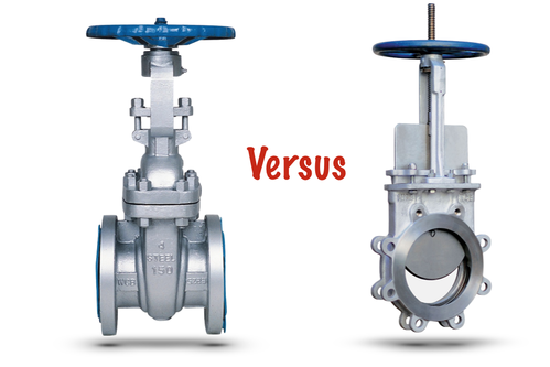
While gate valves and knife gate valves share many similar characteristics, there are some fundamental differences that set them apart. Here we explore the similarities and differences between these useful shut-off valves.
While knife gate valves and gate valves share many similarities – they’re both used in on-off applications, involving slurries and other viscous media – there are some noteworthy design variances to consider when weighing up which type of valve would be best suited for your application.
How do gate valves and knife gate valves work?
Gate valves open by lifting a round or rectangular gate (or wedge) out of the path of the fluid. The sealing surfaces between the gate and seats are planar, so gate valves are often used when a straight-line flow of fluid and minimum restriction is needed. They have a flat gate closure that slides in and out or up and down between two parallel plates to open or close the valve. Gate valves are used for shut-off, rather than flow regulation because they only have two settings: on and off.
While a knife gate valve performs exactly as the name implies. These types of valve were originally designed for the pulp and paper industry. Stringy pulp would impinge between the wedge and seat of a normal gate valve and prevent flow shut-off. Knife gate valves were designed with a sharp edge to cut through the pulp and seal. With this type of useful attribute, the knife gate valve has become invaluable in applications involving slurry, viscous fluids and other systems where impingement is an issue.
Gate valve and knife gate valve applications
Gate valves are used in many industrial applications requiring shut-off valves, including the oil and gas industry, pharmaceuticals, manufacturing and automotive. They can cope in demanding environments, such as high temperature and high pressure environments. Common gate valve applications include in power plants, water treatments, mining and offshore applications.
Knife gate valves are advantageous in sludge and slurry applications because their blades cut right through thick liquids easily. They’re generally specified in larger sizes for handling thick flows of heavy oils, light grease, slurry, paper pulp, varnish and wastewater to name but a few knife gate valve applications.
Advantages and disadvantages of gate and knife gate valves
One of the advantages of gate valves is that pressure drop across a gate valve is very low when it is fully open. They can also be used for bi-directional action and are useful as on-off valves. Gate valves do, however, need a large force to operate and large sized valves need automatic actuators. They’re not quick to open or close, and take up more space, when compared to some other valves. Thermal expansion and shrinking can also lead to unwanted leakage in some gate valves that are exposed to high temperature fluctuations.
The advantages of knife gate valves are that they’re cheap, easy to actuate, and light. One of the most notable disadvantages of knife gate valves is that they’re known to have low-pressure limitations. This makes them less desirable for use in applications that require cleanliness or sanitary conditions.
What is a Non-Return Valve?
Non-Return Valves (also known as check valves or one-way valves) normally allow fluid (liquid or gas) to flow through them in only one direction. These two-port valves have two openings in the body, one for fluid to enter and the other for fluid to leave. Non-Return Valves work automatically, which means that most are not controlled by a person or an external control. Therefore, most do not have a valve handle or stem.
Different types of Non-Return ValvesThe following are all typical styles of Non-Return Valves:
Ball NRVs: have a closing member, the movable part to block the flow, that is a spherical ball. This is sometimes spring-loaded to help keep it shut, or otherwise reverse flow is required to move the ball toward the seat and create a seal. The interior surface of the main seats of ball NRVs are conically-tapered to guide the ball into the seat and form a positive seal when stopping reverse flow. Ball check valves are often very small, simple, and cheap.
Diaphragm NRVs: use a flexing rubber diaphragm to create a normally-closed valve. Pressure on the upstream side must be greater than the pressure on the downstream side (pressure differential) for the NRV to open and allow flow. Once positive pressure stops, the diaphragm automatically flexes back to its original closed position.
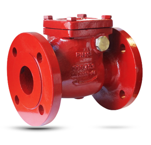
Swing Check NRVs: have a movable part to block the flow, which swings on a hinge or trunnion on to the seat to block reverse flow or off the seat to allow forward flow. The seat opening cross-section may be perpendicular to the centerline between the two ports or at an angle. Although swing check NRVs can come in various sizes, larger NRVs are often swing check valves.
Stop Check NRVs: have override control to stop flow regardless of flow direction or pressure. As well as closing in response to insufficient forward pressure or backflow, it can also be deliberately shut by an external mechanism. This can prevent any flow regardless of forward pressure.
Lift Check NRVs: feature a disc, sometimes called a lift, which can be lifted up off its seat by higher pressure of inlet or upstream fluid to allow flow to the outlet or downstream side. When the pressure drops, gravity or higher downstream pressure causes the disc to lower onto its seat, shutting the valve to stop reverse flow.
In-line NRVs: are similar to a lift-check NRV but generally has a spring that lifts when there is pressure on the upstream side of the valve. The pressure needed on the upstream side of the valve to overcome the spring tension is called the 'cracking pressure'. When the pressure goes below the cracking pressure, the spring will close the valve to prevent back-flow.
Advantages of a Non-Return Valve
Available in a wide range of sizes and costs, NRV valves are generally small, simple and inexpensive. They also protect pumps and compressor equipment from damage caused by backflow and reverse flow. They reduce down time and loss of production due to the failure of unsuitable valves. They increase energy savings, thanks to low pressure drop, and are very effective in preventing water hammer.
Add in the fact that NRVs reduce the possibility of sudden valve failure, and lower maintenance costs due to fewer moving parts, and you can see why they are an excellent choice for water, wastewater and pumping applications.
Different types of Non-Return ValvesThe following are all typical styles of Non-Return Valves:
Ball NRVs: have a closing member, the movable part to block the flow, that is a spherical ball. This is sometimes spring-loaded to help keep it shut, or otherwise reverse flow is required to move the ball toward the seat and create a seal. The interior surface of the main seats of ball NRVs are conically-tapered to guide the ball into the seat and form a positive seal when stopping reverse flow. Ball check valves are often very small, simple, and cheap.
Diaphragm NRVs: use a flexing rubber diaphragm to create a normally-closed valve. Pressure on the upstream side must be greater than the pressure on the downstream side (pressure differential) for the NRV to open and allow flow. Once positive pressure stops, the diaphragm automatically flexes back to its original closed position.
Swing Check NRVs: have a movable part to block the flow, which swings on a hinge or trunnion on to the seat to block reverse flow or off the seat to allow forward flow. The seat opening cross-section may be perpendicular to the centerline between the two ports or at an angle. Although swing check NRVs can come in various sizes, larger NRVs are often swing check valves.
Stop Check NRVs: have override control to stop flow regardless of flow direction or pressure. As well as closing in response to insufficient forward pressure or backflow, it can also be deliberately shut by an external mechanism. This can prevent any flow regardless of forward pressure.
Lift Check NRVs: feature a disc, sometimes called a lift, which can be lifted up off its seat by higher pressure of inlet or upstream fluid to allow flow to the outlet or downstream side. When the pressure drops, gravity or higher downstream pressure causes the disc to lower onto its seat, shutting the valve to stop reverse flow.
In-line NRVs: are similar to a lift-check NRV but generally has a spring that lifts when there is pressure on the upstream side of the valve. The pressure needed on the upstream side of the valve to overcome the spring tension is called the 'cracking pressure'. When the pressure goes below the cracking pressure, the spring will close the valve to prevent back-flow.
Advantages of a Non-Return Valve
Available in a wide range of sizes and costs, NRV valves are generally small, simple and inexpensive. They also protect pumps and compressor equipment from damage caused by backflow and reverse flow. They reduce down time and loss of production due to the failure of unsuitable valves. They increase energy savings, thanks to low pressure drop, and are very effective in preventing water hammer.
Add in the fact that NRVs reduce the possibility of sudden valve failure, and lower maintenance costs due to fewer moving parts, and you can see why they are an excellent choice for water, wastewater and pumping applications.
What is a knife gate valve and what are they used for?
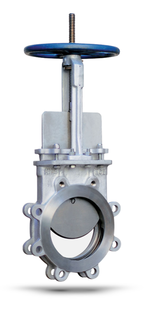
For applications involving slurries, and other thick viscous fluids, a knife gate valve is more often than not an essential component. These specialist shut-off valves cut through slurry media like, well, a knife! Here’s our ultimate guide to the functions and advantages of knife gate valves.
Not only do knife gate valves minimise pressure drop in the fully opened position, but they’re also easy to actuate and offer cost and weight benefits in comparison to standard gate valves. If you’re handling slurries or viscous media, the following overview should make essential reading.
What is a knife gate valve?
Knife gate valves are primarily designed for on-off services in systems that require infrequent use of the valve. They are designed for full-area flow to minimise pressure drop. Since most of the flow change occurs near the shut-off, the relatively high fluid velocity causes disk and seat wear and eventual leakage if the valve is used to regulate flow.
Knife gate valves minimise pressure drop across the valve in the fully opened position and stop the flow of fluid completely. The direction of fluid flow doesn’t alter and the diameter through which the process fluid passes is equal to that of the pipe. This is why they display minimal pressure drop when opened fully.
Knife gate valves also have a very thin profile compared to standard gate valves. They are uni-directional – although bi-directional versions are available – and come in either wafer or lugged body, which means no flanges. The seats on knife gate valves come in a variety of different materials, from metal to resilient types.
Where are knife gate valves used?
Knife gate valves are commonly used in applications involving slurries. This is because their so-called “knife” cuts right through the slurry. They are also used in applications that involve viscous liquids, such as heavy oils, light grease, honey and other non-flammable viscous liquids. Larger sized models are available to better handle thick flow and, whatever the size of valve, knife gate valves are excellent for use anywhere that a shut-off valve is needed.
Advantages of knife gate valves
Knife gate valves benefit from being lightweight, easy to actuate and cheap to produce.
Disadvantages of knife gate valves
Knife gate valves do have low-pressure limitations. They are therefore not ideal for use in applications that require cleanliness or sanitary conditions.
Different types of butterfly valves
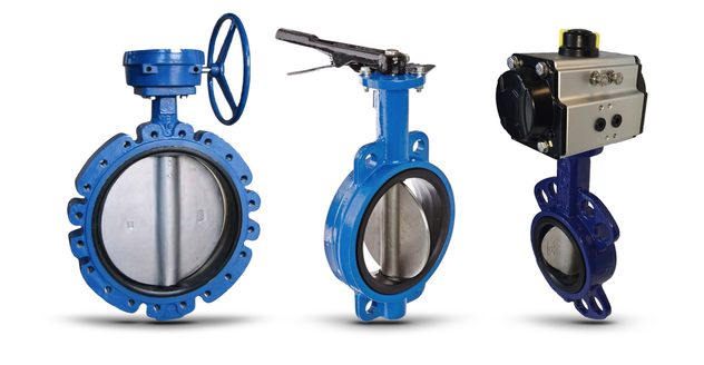
Butterfly valves are commonly used in the pharmaceutical, chemical and food industries to interrupt product flow – such as solid, liquid or gas – within the process. In this article, we explore the different types of butterfly valves available.
What is a butterfly valve?
A butterfly valve either isolates or regulates flow, using a disc closing mechanism. Operation is similar to that of a ball valve, which allows for quick shut off. Butterfly valves are generally favoured though because they are more cost-effective and lightweight than other valve designs. They deliver easier installation and significant cost savings compared to ball valves, especially at lager sizes.
Butterfly valves hail from the quarter-turn valve family. When the disc is rotated a quarter turn, the valve is either fully open or closed. The so-called "butterfly" is a metal disc mounted on a rod and when the valve is closed, the disc is turned such that it completely blocks the passageway. Fully opened, the disc is rotated a quarter turn to allow a near unrestricted passage of the fluid. It can also be opened incrementally to throttle flow.
What are the different types of butterfly valves?
Wafer butterfly valves
Wafer butterfly valves are designed to maintain a seal against bi-directional pressure differential to prevent any backflow in systems designed for unidirectional flow. This is achieved with a tightly fitting seal, such as a gasket, o-ring, precision machined, and a flat valve face on the upstream and downstream sides of the valve.
Lugged butterfly valves
Lugged butterfly valves have threaded inserts at both sides of the valve body, enabling them to be installed in a system using two sets of bolts and no nuts. The valve is installed between two flanges using a separate set of bolts for each flange. This allows either side of the piping system to be disconnected, without disturbing the other side.
Lugged butterfly valves used in dead end service generally have a reduced pressure rating. A lugged butterfly valve mounted between two flanges will have a 150 psi pressure rating. Whereas, the same valve mounted with one flange will have a 75 psi rating in dead end service.
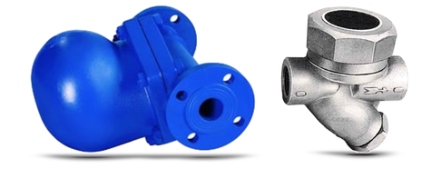
What is a Steam Trap & how do Steam Traps work?
Industrial applications that are powered by steam demand the utmost efficiency to ensure that latent heat is maximised and liquid condensate is removed as quickly as possible. This is where automatic valves, known as steam traps, can prove to be an invaluable ally, as we explain.
What is a steam trap?
Steam traps are a type of automatic valve that filter out condensate and non-condensable gases (such as air) without letting steam escape. They open, close or modulate automatically, discharging condensate as soon as it is formed in an energy efficient manner.
How do steam traps work?
The most basic form of steam trap is a disc, or short solid pipe nipple, with a small hole drilled through it installed at the lowest point of the equipment. Since steam condensate collects at the lowest point, and is around 1200 times greater in volume than hot liquid, condensate is effectively removed and the steam is blocked. The vast majority of steam traps in current operation are mechanical or thermostatically operated. These types of steam traps open when condensate and inert gases need to be removed and close when all the condensate is removed. The process repeats when new steam is condensed and ready to be drained.
Steam traps work best when sized specifically for the application they are used on. Generally, it is better to oversize because they will still discharge condensate when present and close or obstruct for live steam. However, an over-sized steam trap may wear quickly, waste energy and – if drastically over-sized – can cause process issues.
Types of steam trap available:
Mechanical steam traps (such as inverted bucket and float traps) have a float that rises and falls in relation to condensate level. This normally has a mechanical linkage attached that opens and closes the valve. Mechanical traps operate in direct relationship to condensate levels present in the body of the steam trap and have a typical service of life of three years.
Thermodynamic (TD) steam traps work on the difference in dynamic response to velocity changes in flow of compressible and incompressible fluids. As steam enters, static pressure above the disk forces the disk against the valve seat. The static pressure over a large area overcomes the high inlet pressure of the steam. Then, as the steam starts to condense, the pressure against the disk lessens and the trap cycles. This essentially makes a TD trap a 'time cycle' device that will open even if there is only steam present. This can lead to premature wear. Furthermore, if non-condensable gas is trapped on top of the disc, the trap can become locked shut.
How are steam traps used in different applications?
In steam installations, choosing the right type of steam trap can make all the difference in your pursuit of an efficient system that effortlessly drains excess condensate whilst also retaining precious steam. With that in mind, we look at common applications requiring steam traps and talks you through which traps would be optimal for the task. Steam traps are variously needed to drain condensate from steam piping, steam-using process equipment and tracer lines, which calls for slightly different steam trap varieties in each specific case.
Which applications require steam traps?
Drip Applications
Drip applications are the most common application for steam traps. This involves removing condensate formed in steam lines when the steam has lost its heat energy. In these cases, the resulting traps are known as 'drip traps,' which require minimal condensate capacities and don’t necessarily discharge large amounts of air.
Type: Thermodynamic traps are widely used in drip applications because thermostatic air vents in the piping system take care of removing air from the system. For steam systems up to 30 PSIG, Float and thermostatic (F&T) traps are recommended and for steam systems containing excessive scale and dirt, bucket traps are the most reliable option.
Process Applications
Process trap applications involve removing condensate and air from a specific heat transfer process (such as a radiator or heat exchanger). So-called process traps are therefore deployed in process applications that demand larger condensate handling and greater air discharge capabilities.
Type: The most widespread stream trap used for process applications are thermostatic traps and Float traps because they both offer exceptionally good condensate and air handling capabilities.
Why use a ball valve versus a globe valve?
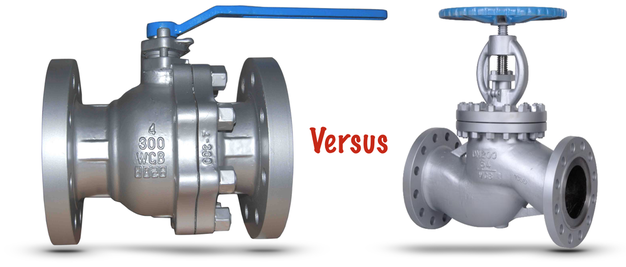
There are many different types of valves available for different applications. With so much choice it can be difficult to decide which valve is most suitable for your application. In this article, we explores the merits of ball valves versus globe valves.
What is the main difference between ball and globe valves?
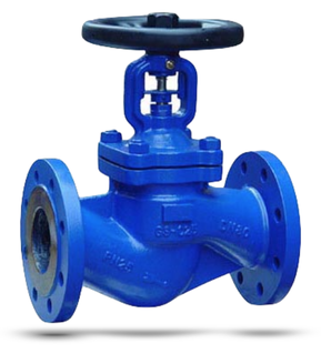
The main difference between ball and globe valves is the way they close. Ball valves have a stem and ball, which turns horizontally, and are commonly referred to as “rotational” valves. Whereas, globe valves have a stem and plug, which strokes linearly, and gives them their other name of “stroke” valves. Ball valves are best suited to applications requiring on/off control without pressure drop. While globe valves excel at regulating flow.
How does a ball valve work?
Ball valves are designed with a ball inside the valve. A ball valve is a form of quarter-turn valve which uses a hollow, perforated and pivoting ball (called a "floating ball") to control flow through it. It is open when the ball's hole is in line with the flow and closed when it is pivoted 90-degrees by the valve handle. The handle lies flat in alignment with the flow when open, and is perpendicular to it when closed, making for easy visual confirmation of the valve's status.
How does a globe valve work?
Globe valves were for many years the industry standard in control valves. They are named for their spherical body shape, with the two halves of the body being separated by an internal baffle. This has an opening that forms a seat onto which a movable plug (or disc) can be screwed in to close the valve. Typically, automated globe valves use smooth stems rather than threaded and are opened and closed by an actuator assembly.
Which is better: a ball valve or globe valve?
Ball valves are durable, performing well after many cycles, and reliable, closing securely even after long periods of disuse. These qualities make them an excellent choice for shutoff applications, where they are often preferred to gates and globe valves. On the flip side, ball valves do lack the fine control in throttling applications offered by globe valves.
What is the main difference between ball and globe valves?
The main difference between ball and globe valves is the way they close. Ball valves have a stem and ball, which turns horizontally, and are commonly referred to as “rotational” valves. Whereas, globe valves have a stem and plug, which strokes linearly, and gives them their other name of “stroke” valves. Ball valves are best suited to applications requiring on/off control without pressure drop. While globe valves excel at regulating flow.
How does a ball valve work?
Ball valves are designed with a ball inside the valve. A ball valve is a form of quarter-turn valve which uses a hollow, perforated and pivoting ball (called a "floating ball") to control flow through it. It is open when the ball's hole is in line with the flow and closed when it is pivoted 90-degrees by the valve handle. The handle lies flat in alignment with the flow when open, and is perpendicular to it when closed, making for easy visual confirmation of the valve's status.
How does a globe valve work?
Globe valves were for many years the industry standard in control valves. They are named for their spherical body shape, with the two halves of the body being separated by an internal baffle. This has an opening that forms a seat onto which a movable plug (or disc) can be screwed in to close the valve. Typically, automated globe valves use smooth stems rather than threaded and are opened and closed by an actuator assembly.
Which is better: a ball valve or globe valve?
Ball valves are durable, performing well after many cycles, and reliable, closing securely even after long periods of disuse. These qualities make them an excellent choice for shutoff applications, where they are often preferred to gates and globe valves. On the flip side, ball valves do lack the fine control in throttling applications offered by globe valves.